
A simple but useful feature has been included in Inventor 2009.... Place Component Orientation. What this allows you to do is place multiple instances of a component into your assembly based on the LAST INSTANCE orientation. That's right....place a component and position it where you like in your assembly based on the last occurrence. An option in the Application Options allows you to place subsequent instances in the assembly in the same orientation as the last placed instance. This will allow you to insert many components into your designs without having a one and only default orientation. This should make it easier to place multiple components in your designs without having to constantly re-orientate it to what your design dictates.
Check out this Short Video to Show You How:
Watch Me
John with the INCAT CAD Geeks.
 As mentioned a few weeks back we all need to create a Digital Prototyping Task List.
Digital Prototyping Task List - #2 "Contact Sets"
Contact sets allow you to check where your assembly interferences take place based on the degrees of freedom. Basically all you need to do it select which parts you want to check, right click turn on Contact Set for each, then use drive and or drag to see where you will interfere with other parts.
Within Document Settings you can also adjust if you want to run this on all parts or just the ones you have in the contact set.
Check out this short highlight video to get you started with DP task #2.
WATCH THIS VIDEOEnjoy,
Kevin with the INCAT CAD Geeks
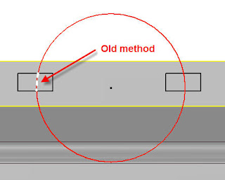
We all know that one person you needs to be the center of attention. When we relate that back  to Inventor we could always display the Center of Gravity (COG) and receive X,Y,Z, but not much more. With 2009 Inventor we have some long awaited abilities to utilize the COG. The COG glyph now displays in a part or assembly model with three planes and a point. You can select the planes or point when measuring from an object to the center of gravity. To select the planes or center point, Selection Priority must be set to Feature Priority or lower. You can also resize the planes of the glyph to better match your visual and selection requirements.
To identify and document the center of gravity location in a drawing view, you can select to have a center mark display at the current calculated center of gravity for the model. The center mark's location is associative to the model and you can add annotation to the center mark. In the past you  may have done this with adding a sketch point or something else to represent the COG.
Check out my video of how to do this.
Submitted by Dave of the INCAT CAD Geeks


Take a look at this video for the general creation and publishing process:
Watch Video

Life is only getting easier with the newest release of Inventor. With the addition of Parts list filters you now have the ability to control which items are displayed in your parts list. Choices you have for filters are: Assembly View Representation, Ballooned Items Only, Item Number Range, Purchased Items and Standard Content. These filters are used in combinations and are available either globally in the Parts List Style, or locally  in the Parts List itself. Check out the video to see these items in action.
Check out my video of how to do this.
http://screencast.com/t/xTzIG6lzRV
Submitted by Dave of the INCAT CAD Geeks


Create your own Digital Prototyping task list .... every spring Inventor adds more and more great new features. However each spring that means you have more to learn. Myself and the rest of the INCAT CAD Geeks are constantly looking for way to help you and our customers take their 3D designs further by learning all the new features. So sometime you have to create a targeted list of things to go and learn, so that is what todays post is all about getting started, but not just for whats new!
Like myself when I first used parametric modeling in the later 90's I was blown away by being able to change my models and it magically updated my drawings. I also loved the fact that drawing creation was a breeze. But over the last few years the tool set has really expanded to add tremendous power right at the fingertips of the designer that really focus on Function more than Form and Fit. So with this post I wanted to START a short list of commands that myself and the INCAT CAD Geek team will highlight in the coming weeks that I feel can empower you to start you own personal "Digital Prototyping Task List" so you can ensure you really taking advantage of your tool set.
Feel free to add more to the list using comments.
Thanks,
Kevin with the INCAT CAD Geeks
- Drive Constraints
- Contact sets and solver
- Auto Limits
- Layout sketches
- Design Accelerators (Tons in this bucket)
- Dyanmic Simulation
- Bolted Connections
- FEA
- More to come......
When working with translated data you may have to perform changes to that data or may have to remodel it since it can’t easily be changed. Autodesk Labs to the rescu e!!! Feature Recognition allows you to take translated data and create a basic history tree. The history tree will include a base sketch, fillets, chamfers, extruded and revolved features, shell and sweep features and sculpt features. They say on the website it works with neutral cad formats like step, sat and iges but I found it works with solid works data and have not tested any other formats at this time.
Check out my video of how to do this.
http://screencast.com/t/zZv4NGHQ
Submitted by Dave of the INCAT CAD Geeks

Every time we design some piece of equipment that has motion to it, we need to show it in multiple positions. Is it OPEN? is it CLOSED? help me understand what this thing is doing?
These are all questions I am sure we have all heard from someone trying to assemble a design or someone from outside of the engineering department, who might not have the print reading savy of you.
Well let us all breath a bit easier now that we can create Positional Representations in Inventor.
We can use those to create overlay views right on a drawing view. This will help realy that difficult information a lot easier.
Check out my VIDEO here:
Enjoy,
Jim.....Another INCAT CAD Geek!
 One of the great new Sheet Metal features to come along with Inventor 2008 was the improved Contour Flange command. This could be used to create some elaborate box type shapes, but it had limitations with internal type flanges. Autodesk is improving the sheet metal environment once again with Inventor 2009, and one of the improvements now allows many types of internal contours.
Contributed by Ben of the INCAT CAD Geeks
Using the iAuthor command may save you a lot of time when creating configurations. You don't need to mess around with the editing tables or .xls spreadsheets unless you want to go crosseyed. You can use the toolbar to toggle between editing a single member at a time or the entire factory scope. Inventor then "captures" the edits you make and will add the neccessary parameters or changes you make to the table. That way you can make the edits in an environment that you are most familiar with....the modeling space.
WATCH VIDEO HERE
It works the same for iAssemblies as it does for iParts making configurations fast and easy.
John with the INCAT CAD Geeks

Submitted by Dave of the INCAT CAD Geeks


 A new option for anyone who has used the trim and extend tools in AutoCAD. Inventor 2009 now allows an explicit selection for cutting edges by holding down the CTL key. This allow a quick trim operation in situations where many picks would have been previously required.


