
August 6th, 2009 | 2:00-3:00 PM EST
Topics to be discussed:
Alias & Inventor workflows
We will show how surface models created in Alias can be natively opened in Inventor, modified, and later updated after changes take place back in Alias.
As always a Q&A session will follow the demonstration allowing all attendees to discuss topics relating to Alias.
Click HERE to register


Autodesk Showcase will allow you and your company to leverage your 3D CAD data with the benefits of high-end visuals.

Let our visualization team show you the power of Showcase by creating an image for you free of charge!

Today we are going to look at the plastic part grill feature in Inventor 2010. You can easily create a rough sketch of what you want and use the options in the create feature box to do the rest. I also really like the real time preview that you get when making adjustments, it helps me see how things are going to turn out before I accept. I also will show another nice feature to create a "rule fillet". This is handy when filleting a lot of edges and not having to select them all. Best part, it isn't limited to plastic part features. Let's take a look....
John with the CAD Geeks

 One of the tricks I find most people are unaware of in Inventor is the ability to edit "Base" features in Inventor. Base features are what you normally get when you import a model from another CAD system or Step file. Many people have figured out that they can sketch on faces of a Base model to create additional features, but few know they can use something as simple as the "Delete" key to remove features while in the Base Editing mode (as detailed in a previous CAD Geek post). I just wanted to show an example of utilizing a work plane and streching a base solid to a wider variation. Take a look at this video for a quick example:
With so many companies having to move to 3d today there can be a lot of out of the pocket expense not only for software but also for training there users also. Autodesk has a great workflow to allow companies to take baby steps in moving to 3D. This workflow will allow a company to model parts inside of Inventor and have the ability to do the detailing work inside of Autocad Mechanical with a direct link to that Inventor model. At the end of the day a company can spend less money on training and software and bring there entire design team up to speed as time permits with 3D. With the direct link to the model file the Autocad Mechanical users will be notified when there detail is out of sync with the Inventor model.

Check it out
http://screencast.com/t/0Xgxn603B
Submitted by Dave of the INCAT CAD Geeks
Nothing was worse when I was a designer having to meet a deadline but did not have the standard parts I needed to complete my design. I had three options spend the time to model the part, which meant finding who had the catalog I needed second option revise something that was similar or hopefully be able to download an iges or step file if it even existed and deal with the black magic of translating. Today from the Inventor interface I have popular manufacture’s catalog data available with native Inventor files. This is not something new but this site has expanded greatly with rich data, again from a large list of manufacturer’s. Check out the Supplier Content Center work inside of your manufacturer's catalog online. Check it out
http://screencast.com/t/IwqwkfnWsB
Submitted by Dave of the INCAT CAD Geeks
How can I improve capacity for large assemblies or drawings?
Please note that Windows allocates Virtual memory to an application. This is the Address Space available to any application. The size of this Address space is a function of the design of the operating system, not the physical memory installed on the system. More physical memory will increase performance, but not address space. Inventor, like any Windows application, is limited by the address space allocated to it by the Windows Operating System. Whatever the limit, Inventor users may run into it. A warning will be issued when you reach 80% of the available address space. It is advisable to save your work as soon as possible. When windows issues a message that a memory request has been denied, Inventor is no longer intact.At the 80% warning, exit Inventor saving your results. Restart Inventor and re-load your work. This removes memory allocations that are no longer needed because that work has been accomplished.
In a 32-bit computer (as Windows XP is) there is 4GB of memory address space.
2GB of this address space is reserved for the system. 2GB is reserved for the applications. When you add the /3GB switch to the boot.ini, it is taking 1GB of available address space reserved for the OS and giving it to the applications.
This can provide better performance for memory intensive programs like Inventor. However, there could be potential side-effects for the system of course. But nothing too much to worry about, or otherwise it would never be recommended. The boot.ini file is how you enable the option for the 3GB switch. It allows the 2GB that is dedicated to the system to give up 1GB and add it to the 2GB that is dedicated to the applications.
See the example boot.ini file below:
[boot loader]
timeout=5
default=multi(0)disk(0)rdisk(0)partition(1)\WINDOWS
[operating systems]
multi(0)disk(0)rdisk(0)partition(1)\WINDOWS="Microsoft Windows XP Professional" /fastdetect /NoExecute=OptIn
multi(0)disk(0)rdisk(0)partition(1)\WINDOWS="Microsoft Windows XP Professional /3GB Switch" /3GB /fastdetect
****Before changing your boot.ini file save a backup****
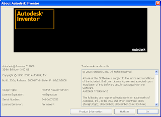
Follow the video on how to do this remember once you have made the change to your boot file you must restart your system. When your system reboots you will have a choice to select the 3 gig environment. Launch Inventor, go to the Help pull down menu and select about Autodesk Inventor to confirm Inventor has recognized the switch. Information provided from a AUGI Forum.
****Before changing your boot.ini file save a backup****
Follow the video on how to do this remember once you have made the change to your boot file you must restart your system. When your system reboots you will have a choice to select the 3 gig environment. Launch Inventor, go to the Help pull down menu and select about Autodesk Inventor to confirm Inventor has recognized the switch. Information provided from a AUGI Forum.
Check it out
http://screencast.com/t/Nefm3OT67
Submitted by Dave of the INCAT CAD Geeks

Well now that I have your attention....I was at one of my customers this week and they are heavy into making molds. Not for Blue Cheese either, the kind for making injection molded parts.
They get files from all sorts of CAD software and want to simplify how they make mold parts for the cavities.
Here is a simple way to start doing this in Inventor today. We started with a derived component, and the sculpt command.
Enjoy,
Jim.....Another INCAT CAD Geek!

You may have seen the infomercial or not, it rings a bell for me working those long hours completing task I just did not have time to complete at work, Task Scheduler to the rescue. This functionality gives me the ability to schedule common task when I am away from my machine. Task like: Migrating files, Updating a design, publishing dwf’s, printing, importing and exporting files, check into and out of vault, retrieving latest versions from vault and converting idw’s to dwg’s. Set up a single task or run multiples at once you pick the time and day.
Check out my video of how to do this.
Submitted by Dave of the INCAT CAD Geeks
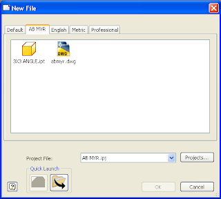
Templates are not just used for setting drawing and part standards. I have found a great use working with commonly used parts in a design, in this case I never know the actual length of my given part and it may change throughout my design creation. My video shows the creation of this part template and working with it inside my design. In this case I could have taken advantage of frame generator but at times that functionality does have limitations. Remember any part you choose to use as a template must be saved in a template folder.
Check out my video of how to do this.
http://screencast.com/t/kkGMf0o1i0
Submitted by Dave of the INCAT CAD Geeks
Last week we hosted the first ever Inventor web based user group meeting. Over the last 4 years here at INCAT myself and my team have launched 5 land based user groups and 3 web based user groups. Last week was the kick off for the Inventor web based one, where as the other two focus on Data Management and AutoCAD Electrical. Learn more about our user groups HERE
We covered 4 topics:
- 3d Grips
- Imate basics
- icheck for Inventor (3d CAD Standards Checker)
- Highlighted a few Inventor 2009 new features
The recording of the webcast will be posted HERE and if you would like to sign up for future emails about our user groups please take this SURVEY Even if you didn't make the meeting, this survey will allow you to tell us if you want future notifications about user groups etc.
Thanks and hopefully you can join us for a future meeting.
Kevin with the INCAT CAD Geeks

I've often been asked how easy is it to create an exploded view to send to someone to clarify a design. Well, for most small assemblies, it's almost too easy. Check out my video on how to create an exploded view with different sequences, camera angles and assembly instructions. Then, it's published to DWF for sharing with anyone. Notice how the DWF captures everything you have in Inventor.... complete with the parts needed for each step of assembly.
I wish they would include this with some of my kids toys I have to put together!
John with the INCAT Cad Geeks

Well, I'm on the road again. What benefit does that have? I get to learn more about how actual users are USING Inventor in their day to day activities. It also allows me to make their job easier by showing them things that may be under their noses but they don't understand how to fully use it. For instance, take the selection filters in Inventor. Too often I see users using AutoCAD commands (window, ctrl key, picking individual, etc.) to select objects in their assemblies. There are a wide variety of selection filters based on what you really want to select waiting for you to explore.
Check out the video to see just a few of them in action.
Happy Picking!
John with the INCAT CAD Geeks

Depending on what you need to select within your parts and assemblies you have tons of choices. Considering the task at hand you might want to select a sketch and not a face, or a feature and not a part when you’re in an assembly. Take a look at this video for a few examples.
Enjoy
Kevin with the INCAT CAD Geeks
Enjoy
Kevin with the INCAT CAD Geeks
View VIDEO HERE
I have been asked many times while onsite how to make a sheet metal cone. I will show you one method to produce a flat pattern for a sheet metal cone.
The first step is to draw my basic sketch in this case I will use the idea that my opening will be 3” at the top and 5” on the bottom. Once completed, I will revolve my sketch around my origin Y axis making sure I am not at a full 360 degrees. The small opening that will be created by not fully revolving the section will allow Inventor to be able to flatten the cone. Remember, a quick short cut to the revolve command will be to select "R" from the keyboard. Once created you will convert your standard .ipt file into a sheet metal file and make sure to change your metal thickness in the sheet metal styles to match your sketch. To create the flat pattern you will need to select the inner or outer face of the cone, and then select the flat pattern command. This is one way to create a sheet metal cone, but there are many others. Have fun with it and find the best way to suit your needs.
Check out my video of how to do this.
http://screencast.com/t/FgUjPLdpHN
Enjoy,
Dave Another one of the INCAT CAD Geeks
 One of the features that you may have read about when Inventor 2008 was released was a new "Face Fillet" option in Inventor's usual Fillet command. The face fillet option will allow a fillet to be created between two faces that don't even share a common edge! If you haven't seen the new tool in action, take a look at the following video for a quick example:
http://screencast.com/t/LTFD6eYZIy
Until next time,
Ben with the Incat CAD Geeks
To continue the series here are few more reasons why MDT users need to make the move.
- Inventor Graphics - OK when AutoCAD came out it was cool, but 25 years later you need a more up to date way to look at 3d models, and the Inventor Graphics are light years ahead of the MDT/AutoCAD based graphics.
Sample Image -http://screencast.com/t/CZqI4eSqK
- Inventor Studio - Rendering! not shading:) Inventor has photorealisitic rendering built right in. Once you model a part or assembly you are only about 5 clicks away from a photorealisitic rendering.
Sample Image - http://screencast.com/t/uSJ14n89FM
- Feature Previews - Within MDT you can only rely on the image within the dialog boxes to try and figure out the impact a feature will have before you add it. Within Inventor you get real time previews on almost every feature type, even lofts!
Sample Image - http://screencast.com/t/vCUTygPi
Enjoy
Kevin with the INCAT CAD Geeks
Anytime I work with customers using the frame generator tool inside Inventor I am asked how to customize the information being displayed. An example of this would be that your company requires the part number to be the stock number and that you also need to display the total length of a given object for that part number. Today you maybe manually entering a part number and maintaining the proper length this can be time-consuming and error-prone task. With the use of simple expressions inside the Bill of Materials dialog box these task are made simple and automatic. The following illustrations show the before and after.
 Check out my video of how to do this.
http://screencast.com/t/NpiyyU6yXh
Enjoy,
Dave Another one of the INCAT CAD Geeks

Back when I had a real job as a designer, I always hated having to sort through my complicated assembly views. Well with Inventor, you can pick and choose which parts in the view show up with or without hidden lines. This can take that very complicated view and make it a lot simpler to relay the exact information that you want.
Check out my video of how to do this.
http://www.screencast.com/t/lJ0Gjs2M
Enjoy,
Jim
Another one of the INCAT CAD Geeks
Check out my video of how to do this.
http://www.screencast.com/t/lJ0Gjs2M
Enjoy,
Jim
Another one of the INCAT CAD Geeks

I was recently asked how to dimension to Apparent Intersection within an Inventor IDW.
I thought I would post since I do recall learning this for the first time and it was one of those commands that isn't very discoverable. :(
Link to Video to see how
Hope this helps
Kevin with the INCAT CAD Geeks


