
 Parts, assemblies, or sub-assemblies can be used as reference in our models. This means their Bill of Materials structure is set to reference. Reference models are commonly items that we are designing around, and don't want to show up on our manufacturing BOM. These could be supplied by outside sources or modeled up ourselves. These models show up by default as reference lines in an Inventor drawing view. Did you know there are also a number of other options available to control those reference models in the drawing view. Perhaps you want to show them as solid lines, or they keep getting cut off in the drawing view, maybe you don't want to show them at all. It seems like I have been getting a lot of questions about this lately so I thought I would share a deeper look into the referenced model as used in an Inventor drawing.


The ability to blend fillets and similar feature has been increasing over the years, but Autodesk has really outdone itself with the automatic blending that occurs when using the "move face" command. Moving a feature with fillets to an area on the part that also contains fillets will cause a blended region to occur automatically. Whats more, you can even see this occur in the real time preview so you know exactly what you are going to get as a result.


What does your Content Center look like? Many Inventor Content Centers I see will look different based on how many CC Libraries are installed, or have been created custom. All those Content Center libraries can be a lot to sort through when building a set of Favorites or when searching for a certain part. Content Center Filters are a great way to filter based on standard or user created libraries and categories. Do this before creating a list of Content Center favorites and you can save your self a lot of time. The two Content Center features work great hand in hand. Today we'll look at Filters. Next week we'll visit Favorites.
In todays day and age we are all very busy, and it seems we dont have much extra time. I have put together a video that will take you through a high level look at Autodesk Inventor 2011 What's New in under 30 minutes. Of course this is not everything but should be enough to spark your interest to learn more. A few short slides and some clicks and picks, will have you wanting more information.
Let's take a look!!!
http://my.brainshark.com/Inventor-2011-30-Minutes-or-Less-450754882
Created by Dave one of the Cad Geeks

This feature was new to Inventor 2010 and with the next release on the way, I wanted to get this one in our blog. User Coordinate Systems in Inventor. I have found many interesting ways to implement this for customers over the year. In a single part you can use this to locate a new 0X,0Y,0Z, or just locate a specific connection point. Then in the assembly this works great for constraining parts together based on that known point instead of using three or more assembly constraints. This can be done easily using the Constraint Set constraint in the assembly environment. It allows you to quickly put components together based on mating UCS axis, and planes in a few clicks.
Free Move

Video link:
http://www.screencast.com/t/YjgzMjk1MD
Created by one of the Cad Geeks
So you are running an FEA analysis in Inventor, and you need to apply a load to a cylindrical face. Do you use a regular "Force Load" or a "Bearing Load"? The answer really depends on how the force should be distributed on the face in question. A bearing load will apply the load in a parabolic distribution, while the force load will be an even distribution.
Huh?
OK, lets take a look at a couple of loading scenarios and the results that each provides. I have used the shock tube from one of the Inventor sample files as an example.
In the first analysis I used a Force Load. Notice that the stress is not centered on the cylindrical face, but rather along its edges as if the cylinder was being stretched.


You create multiple solid bodies in a part file using modeling commands, or by importing one or more solids using the Derived Component command. Use the Move Bodies command to reposition solid body components.
There are three modes of moving bodies in a part file:
Free Drag allows you to move objects in any X, Y, Z combination.
Move along ray allows you to perform a linear move on objects.
Rotate allows you to set the angular rotation of an object around a central axis.
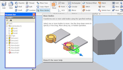
Video link: http://www.screencast.com/t/MzJiOGE3Y Created by one of the Cad Geeks
What is a sheet metal rule?
Sheet metal rules include:
• sheet material and thickness
• bend and corner relief preferences
• miter, rip and seam gap value
• unfolding rule selection
• flat pattern punch representation (applied by default to sheet metal features during flat pattern creation)
• flat pattern bend angle reporting preference

•Easy way to organize sheet metal design properties that are unique to multiple vendors
• Consistency across designs
• Consistency in a multi-user environments
Being on the latest and greatest technology of course has many advantages but at times some disadvantages come along for the ride. One I am seeing is the time needed to take you Inventor drawing formats and save them back to an earlier version of a AutoCAD dwg.
Reasons for Export:
1. Customer requires delivery of all flat AutoCAD format DWG files
2. Vendors need Drawings in AutoCAD format for NC fabrication
3. Shop floor requires AutoCAD DWG for its own fabrication drawings
What can be done:
• Inventor .idw or .dwg exported to Flat AutoCAD file
• DWG or DXF
• AutoCAD 12 DXF
• AutoCAD 2000 to 2010 DWG
Please view the video to watch and learn about the steps needed to batch process this type of conversion.
Video link: http://www.screencast.com/t/ZGQwMWM2YWU Created by one of the Cad Geeks
Every time I use the Dynamic Simulation environment in Autodesk Inventor Simulation, it seems like I have to alter my assembly constraints to get the results I want. This is usually because of redundant assembly constraints. As an example, lets consider a basic four bar linkage. If you constrain the members with all "insert" type assembly constraints, it may act like you want in the normal Inventor environment, but there is actually a redundant planer constraint in this case. Instead, one of the "insert" constraints should be changed to a "axis/axis" mate constraint.
Shown above is another potentially more troublesome pitfall. This occurs when trying to solve simulations where linkage components serve the same purpose and share loads equally. An example of this could be trying to solve both sides of a scissor lift simultaneously. A better approach would be to only use one half of the model in the simulation and simple divide the input loads in half as well. This allows proper calculation by the simulation tool and allows output of the reaction loads desired.
Contributed by Ben of the Tata Technologies CAD Geeks


As many of us are all aware the Autodesk Inventor product line comes with many great translators. We have found many companies today are switching to Autodesk Inventor as a primary design tool because of the powerful translators that allow them to import and export data from the so called high end systems. At the same time giving them the functionality these high end systems have at a much lower operating expense. With this comes the need to translate this data all at once or a batch process. Autodesk Inventor Task Scheduler allows us to batch process this data immediately or at a scheduled time. Lets take a look at the process and the file types Task Scheduler allows us to import and export.
Video Link:
Autodesk Inventor Translators - Batch Import and Export
Created by one of the Cad Geeks
I just wanted to take a look at the Contour Roll command inside Inventor 2010. Of course this command will be found in the sheet metal environment, and by the way you can make some really cool shapes with it. So what is a contour flange:
A contour flange is defined using a profile sketch and a straight edge on an existing face. The profile sketch consists of lines, arcs, splines, and elliptical arcs. Contiguous geometry in the profile results in bends in the contour which honor the bend radius value of the sheet metal style. The contour flange can be offset to either side of the profile sketch.
We see a lot of manually drawn rectangular borders in Autodesk Inventor when we visit customers. The Drawing Border Wizard can aid in creating simple rectangular borders, not just ones with zones. These will also update parametrically with the sheet size, based on the margin offsets:

 In my travels I still see a lot users thinking they need a separate template file for each sheet size. This isn't wrong, it works well for AutoCAD but Inventor has a solution and they're called Sheet Formats!
Tata Technologies recently conducted an “Intro To Design Automation With Autodesk Inventor” webinar. This webinar is currently still available for review at: https://www2.gotomeeting.com/register/683034715
To review any past webinars you can find them at: http://www.tatatechnologies.com/autodesk/Webcast_Download.asp?Menu=Vid
This Automation webcast offered a look into a scalable and affordable path for adding design automation to your Autodesk Inventor workflows. Adding Automation to your design practices has some tremendous benefits like:
• Repetitive tasks done faster / more efficiently
• Reduce order-engineering throughput time
• Reduce order-engineering resources / costs
• Better Sales effectiveness
• Improved quality through consistency
We have also found from a short survey that many companies try to add some level of automation but never fully follow through with the idea due to:
• Knowledge
• Time
• Budget
As covered in the Design Automation with Autodesk Inventor webinar there are 3 ways of adding automation while using Autodesk Inventor:
• Inventor’s native tools
• Inventor iLogic
• Inventor Automation Professional
All 3 options allow for a scalable solution that build on one another and may only take a little time, knowledge and budget to quickly start realizing the benefits of automation.
At Tata Technologies we stand firm on the idea that an educated customer is our best customer. We provide our customers options during the process of investigating our products and services to allow the customer as much information as possible. If you would like to learn more:
• Request a phone call from one of our application engineers to talk about the technology and understand how it will benefit one’s business.
• Schedule a demonstration of Automation Technology
• Email us at cadgeeks@tatatechnologies.com for either of the above or any other needs.
Tata Technologies looks forward to working with you on all your future technical needs!!!
Have a safe and Happy Holiday,
The Tata Technologies CAD Geek Team
If you want quick access to the iProperties command, you can have an iProperties button showing in the Inventor 2010 interface at all times:
Created by a resurrected CAD Geek.


