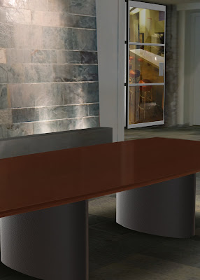
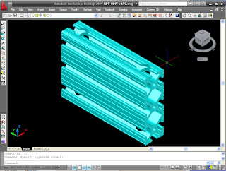
So............I have been working the AutoCAD/Inventor ranks for the last 10 years or so. Every couple years new technology shows up on the scene that really recaptures my free time. Most recently the technology has been Autodesk Showcase. This cool product came to the Autodesk MSD family when the bought up Alias. So be sure and check out the product link above to learn more after you see this cool command called side by side.
BTW - Showcase Imports Inventor Data, and almost any other 3d format!
The Side by Side command, as the name indicates, lets you take two showcase scenes and compare all the different elements of each. Before I joined the reseller world I was required to create design concepts and share them with the sales team and or customers. Not that this was a bad thing, but I always had to pre-plan every possible viewpoint or dataset the would want to look at. Within Autodesk Showcase I can now have real time rendering and show off my concepts using the Side by Side.
Check out the video here:
Go straight to tips and tricks for the following Autodesk Products:
Side by Side Compare with Autodesk Showcase Pro. 2009
Written by Tata Technologies CAD/PLM Geek on Friday, June 27, 2008
Tata Technologies CAD/PLM Geek
Friday, June 27, 2008
![]()
![]()
Labels: Autodesk Showcase
Be more Productive While Sharing Work - iCheck
Written by Tata Technologies CAD/PLM Geek on Thursday, June 26, 2008
I quickly wanted to go over one of my favorite checks that are possible of the 70 available with using iCheck. I have a little scenario and also the benefits of just using this one check.
Like many companies we share our work throughout our group. With doing this every designer creates there assemblies differently on how they may constrain or even ground components into position. I have recently been assigned to take over an assembly a co-worker was working on that I need to finalize and also run through dynamic simulation. Before I can even get started I must spend time upfront to understand how he had created his assembly this can add hours to any job depending on the size.
 Conclusion
Before i-Check I had to manually go through an assembly and verify multiple items before I could move on finishing the design. These items consisted of:
1) Making sure only one component is grounded in my design.
a) This is important due to my first component placed in an assembly sets up my orientation of all subsequent parts and sub assemblies.
b) If components are grounded together instead of constrained its hard to tell if I have proper hole alignment, or have part interference.
c) If using Dynamic Simulation all parts that are grounded in my assembly environment automatically get grounded once I switch to my simulation environment adding additional work when setting up and assembly to run simulation on.
With i-Check with a couple clicks of my mouse I have a report telling me exactly the condition of my assembly. Saving me valuable time upfront interrogating an assembly which now I can spend being productive.
Check it out
http://screencast.com/t/1921SKKdr
Submitted by Dave of the INCAT CAD Geeks
Tata Technologies CAD/PLM Geek
Thursday, June 26, 2008
![]()
![]()
Labels: Autodesk Inventor , errors , icheck
Move off MDT already....Inventor is the way to go - Part 3
Written by Tata Technologies CAD/PLM Geek on Wednesday, June 25, 2008
Tata Technologies CAD/PLM Geek
Wednesday, June 25, 2008
![]()
![]()
Labels: MDT , Mechanical Desktop
What's Your Favorite Environment
Written by Tata Technologies CAD/PLM Geek on Tuesday, June 24, 2008


A nice picture always requires a nice background, and the Alias Design Community has some great example Showcase and Alias Studio environments available for free download. Take a look at the following site and check out the downloads area.
Contributed by Ben of the INCAT CAD Geeks
Tata Technologies CAD/PLM Geek
Tuesday, June 24, 2008
![]()
![]()
Labels: Autodesk Showcase , Environments , Visualization
Stop Constraining Common Parts Use iMate
Written by Tata Technologies CAD/PLM Geek on Thursday, June 19, 2008
 I see a lot of Inventor users spending time constraining commonly used parts. Utilizing iMate functionality can save time when constraining these commonly used parts. The idea of iMates is to create half of the constraint lets say on a library component which only needs to be done once, then the other half of the constraint to any item that may need that part constrained to it. You also have the ability to create groups of iMates called composites. With this you select a group of iMates from the browser right click and select create composite. You have multiple ways of controlling placement of iMates when inserting components into an assembly. If you are adding such a component and it has multiple placements inside of your design do a simple right click of your mouse to bring up some options for placement. From here you could just select place all matching iMates this will solve all matches; you have other options for filtering your selection also.
Tata Technologies CAD/PLM Geek
Thursday, June 19, 2008
![]()
![]()
Labels: Autodesk Inventor , imates
Inventor 2009 - Fixing those Bad Corners....Sheet Metal that is.
Written by Tata Technologies CAD/PLM Geek on Wednesday, June 18, 2008
Tata Technologies CAD/PLM Geek
Wednesday, June 18, 2008
![]()
![]()
Labels: Autodesk Inventor 2009 , Sheet Metal
Can't Figure out a model's Assembly Contraints? Check out iMap on Autodesk Labs.
Written by Tata Technologies CAD/PLM Geek on Tuesday, June 17, 2008
Tata Technologies CAD/PLM Geek
Tuesday, June 17, 2008
![]()
![]()
Labels: Assembly , Autodesk Inventor 2009 , Constraints , iMap
Autodesk Labs is back at it again........Inventor 2009 User Interface Technology Preview
Written by Tata Technologies CAD/PLM Geek on Tuesday, June 17, 2008
Last Friday I posted in advance letting you know that something cool would be coming out early this week. So here it is:
"UI Technology Preview for Autodesk Inventor 2009"
This easy to download tool will run side by side with Inventor 2009 allowing you to check this new interface concept for Autodesk Inventor. Last December while at Autodesk University I was allowed to do some prototype reviews with the Inventor product design team, and I love the new updates. Like anything working through change is tough, but I like the enhanced UI so far.
Stay tuned for more updates as we dig deeper.
Kevin with the INCAT CAD Geeks
Description from the labs web site:
Brand new look and feel for Inventor 2009!
The UI Technology Preview showcases the latest user interface design concepts for Autodesk Inventor 2009 specifically focused at enhancing the user experience. Along with presenting a fresh, modern look and feel to Inventor® 2009, the primary goals of these enhancements are improving usability and learnability for new users and realizing productivity gains for existing users.The UI Technology Preview on Autodesk Labs affords us an excellent opportunity to gather valuable user feedback on these design concepts to help us meet our goals.
Some highlights of the UI Technology Preview for Inventor 2009:
Ribbon style logical grouping of commands - The UI Technology Preview incorporates a ribbon-style layout for accessing familiar Inventor 2009 commands
Quick Access Toolbar for frequently used commands - The UI Technology Preview allows users to put commonly used commands on a Quick Access Toolbar available at all times
Progressive tooltips for greater learnability - Hovering over commands opens progressive tooltips; first level describes the command and second level includes an illustrative explanation
Tabs to quickly switch active documents - The UI Technology Preview offers document tabs with rich previews that allow users to quickly identify and switch between various open documents
Fast facts about UI Technology Preview for Inventor 2009:
Inventor 2009 required for UI Technology Preview - The UI Technology Preview requires an existing installation of Inventor 2009 (Suite, Simulation Suite, Routed Systems Suite or Professional)
Inventor 2009 standard UI and the UI Technology Preview work in parallel - The UI Technology Preview installs in a way that users can use both interfaces in parallel if they prefer
No impact on existing installation of Inventor 2009 - The UI Technology Preview can be installed and uninstalled without any impact on the existing installation of Inventor 2009
No migration impact on Inventor 2009 files - Files can be created, opened and modified in either
Inventor 2009 or the Technology Preview with no need for file migration at any time
English only but installs with all languages - The UI Technology Preview is currently available in English only but will install with all language versions of Inventor 2009
Tata Technologies CAD/PLM Geek
Tuesday, June 17, 2008
![]()
![]()
Labels: Autodesk Inventor 2009 , Autodesk Labs , Technology Preview
No Thanks, I'll Defer....with Autodesk Inventor 2009
Written by Tata Technologies CAD/PLM Geek on Monday, June 16, 2008
Tata Technologies CAD/PLM Geek
Monday, June 16, 2008
![]()
![]()
Labels: Autodesk Inventor 2009 , Autodesk Inventor Professional , Routed Systems
Stay Tuned........Cool new technology preview coming next week
Written by Tata Technologies CAD/PLM Geek on Friday, June 13, 2008
I cant say anything else today, but stayed tuned for a post early next week about some cool new work flows for Autodesk Inventor for you to check out. I know, I know, this blog post wasn't a tip or trick, but I am so busy thinking about my post for next week.......However I might demo this stuff live at our web based user group meeting next Wednesday at 11:30am:
SIGN UP HERE
Stay tuned,
Kevin with the INCAT CAD Geeks
Tata Technologies CAD/PLM Geek
Friday, June 13, 2008
![]()
![]()
Labels: Autodesk Inventor 2009 , Autodesk Labs , Inventor web user group
Added Functionality - Drawing Tools
Written by Tata Technologies CAD/PLM Geek on Thursday, June 12, 2008
Digging a little deeper into those folders I traditionally over look that come with your Inventor media. I was surprised with a ton of great functionality. The latest one I have been playing with are those listed under drawing tools. C:\Program Files\Autodesk\Inventor 2009\SDK\UserTools\DrawingTools. Here I found 3 handy items: Chain Dimension which can relieve you of some tedious work, Alpha Sort for automatically putting your drawings into alphabetical order and revision cloud a lot of people like the idea of using the revision clouds with Design Review I can add revision clouds right from Inventor I just don’t have the selection like I do with Design Review. With this it will create a sketch under the view that I will be applying it to. I thought it would be really cool if I could use crop view with it but unfortunately you can’t.
 Check it out
http://screencast.com/t/9Ya8JlOzFl
Submitted by Dave of the INCAT CAD Geeks
Tata Technologies CAD/PLM Geek
Thursday, June 12, 2008
![]()
![]()
Labels: Autodesk Inventor 2009 , Drawings , SDK , Tools
Arc Text....Another cool feature in Inventor 2009
Written by Tata Technologies CAD/PLM Geek on Wednesday, June 11, 2008
Enjoy,
Jim.........Another INCAT CAD Geek!
Tata Technologies CAD/PLM Geek
Wednesday, June 11, 2008
![]()
![]()
Labels: Autodesk Inventor 2009 , Sketching , Text
Custom iProperty formatting and iProperty expressions
Written by Tata Technologies CAD/PLM Geek on Wednesday, June 11, 2008

Some behind the scenes functionality has been added to Inventor 2009's iProperties that could easily be missed if you don't dig hard enough. Not to worry; check out this video for examples of the new Custom Parameter formatting and how that translates into your Bill of Materials.
Contributed by Ben of the INCAT CAD Geeks
Tata Technologies CAD/PLM Geek
Wednesday, June 11, 2008
![]()
![]()
Labels: expressions , iproperties , Parameter Format
Autodesk Inventor 2D - 3D - YES!
Written by Tata Technologies CAD/PLM Geek on Monday, June 09, 2008
- How easy is it to use my 2D data and convert it to 3D?
- We have over-ridden dimensions in AutoCAD. How will Inventor handle it?
- Can I specify a base point when bringing in AutoCAD 2D data into Inventor?
So as you can see, it's as easy as 1,2,3.
John with the INCAT CAD Geeks
Tata Technologies CAD/PLM Geek
Monday, June 09, 2008
![]()
![]()
Labels: 2D , Autodesk Inventor
Death to sticky notes......Capture your design decisions with Autodesk Inventors Engineering Notebook
Written by Tata Technologies CAD/PLM Geek on Friday, June 06, 2008
Everyday as designers you are faced with trying to recall and remember all the reasons why your designs went from one iteration to another. Instead of jotting down sticky notes and putting them on your LCD, put them on your model with Autodesk Inventors Engineering Notebook. This command has been in Inventor forever, but often overlooked, or maybe I am just a fan :). Either way check out this video for a short example of using CAD sticky notes with Engineering Notebook.
WATCH VIDEO HERE
Enjoy,
Kevin with the INCAT CAD GEEKS
Tata Technologies CAD/PLM Geek
Friday, June 06, 2008
![]()
![]()
Labels: Autodesk Inventor , Engineering Notebook , Idea capture
Bridge the Link
Written by Tata Technologies CAD/PLM Geek on Thursday, June 05, 2008
With so many companies having to move to 3d today there can be a lot of out of the pocket expense not only for software but also for training there users also. Autodesk has a great workflow to allow companies to take baby steps in moving to 3D. This workflow will allow a company to model parts inside of Inventor and have the ability to do the detailing work inside of Autocad Mechanical with a direct link to that Inventor model. At the end of the day a company can spend less money on training and software and bring there entire design team up to speed as time permits with 3D. With the direct link to the model file the Autocad Mechanical users will be notified when there detail is out of sync with the Inventor model.

Check it out
http://screencast.com/t/0Xgxn603B
Submitted by Dave of the INCAT CAD Geeks
Tata Technologies CAD/PLM Geek
Thursday, June 05, 2008
![]()
![]()
Labels: 2D , 3D , Autocad Mechanical , Inventor , Link
Let's Fasten that Sheet Metal PEM Style
Written by Tata Technologies CAD/PLM Geek on Wednesday, June 04, 2008
Tata Technologies CAD/PLM Geek
Wednesday, June 04, 2008
![]()
![]()
Labels: Autodesk Inventor 2009 , bolted connection , Sheet Metal
New Capacity Meter options in Inventor 2009
Written by Tata Technologies CAD/PLM Geek on Tuesday, June 03, 2008
The Capacity Meter provides several pieces of information with regards to memory consumption. The meter has three indicators: total number of occurrences in the active document, total number of files open in the session, and amount of memory used by the session.
The meter can be used in one of two settings: Inventor Only, and Physical Memory.
Inventor Only: Restricts the display to just the Autodesk Inventor process. The color will change from green to yellow when more than 60% of the allotted space is used, then red once 80% has been used. This mode is not available in 64 bit operating systems.
Physical Memory: Adjusts the display to the entire physical RAM. The green portion represents the Inventor session, while the yellow portion is all other applications.
When hovering over the Capacity Meter, the tooltip displays details of used and available memory.
Note: The Physical Memory option is disabled if your Microsoft Windows account is not Administrator, or if Process Monitors have been restricted.
Tata Technologies CAD/PLM Geek
Tuesday, June 03, 2008
![]()
![]()
Labels: Autodesk Inventor 2009 , Capacity Meter


