

The Tube Flange Tool allows you to quickly finish off the edge of a surface by creating fillet and flange surfaces.
Click HERE to watch the video...
Created by Aaron... Your Alias CAD Geek!
Something new in 2010 Electrical is the ability inside of the circuit builder tool to create one-line circuits.
AutoCAD Electrical now provides library support and software support to create motor control one-line diagrams that link back to other drawing types in a project drawing set.
- New motor control one-line symbol library accessible from the icon menu.
- Circuit Builder supports building motor control one-line circuits dynamically allowing the design of one-line circuits, with component values and wire sizes, to conform to a given electrical code.
- One-line component symbols can be related to parent/child counterparts on the schematic and panel layout drawings within a project. You can surf between one-line and related components and all related components update if one is modified.
- Tagging of schematic or panel components using existing commands can reference a pick list that includes components pulled from the one-line diagrams.
- Certain schematic reports have a new category option. You select the category, for example One-Line, and the data is filtered based on that category. It can also be used to filter a report for Hydraulic, P&ID, or Pneumatic components.


Let's Take a Look!!!
http://www.screencast.com/t/3D1Goulmp
Created by Dave one of the Cad Geeks
How to keep track of important points in AutoCAD with OBJECT SNAP TRACKING!
ê Object Snap Tracking (OTRACK) is used for exact selection of points relative to other points in your drawing without needing construction lines. You can track up to 7 points at one time! These can be tracked horizontally, vertically, or at polar alignments based off the points.
ê Access: Make sure the OTRACK icon in the Status Bar is ON and touch the Osnap (ie. HOVER, Do Not Click on it), then click when you reach the desired point location.


In Part 2 of the icheckit entry, we are going to take a look at the part checking features of the software. Here we can look at specific geometry of the part or attributes. icheckit ensures that part models are consistant with your design guidlines and are in compliance with your company standards. In what would be a time consuming, labor intensive, investigative tasks, can easily be conducted with a click of the mouse and running icheckit. Checks can be easily configured to meet your specific needs....Let's "check" it out.....
CAD Geek John

This week I will talk about the difference between Radial and Chordal fillets in Alias. I will also talk about one of the new features of the surface fillet tool in Alias 2010.
Click HERE to watch the video
Created by Aaron... Your Alias CAD Geek!

You can predefine a wire network's connection sequence. This sequence is taken into account by the AutoCAD Electrical wire and cable from/to reporting and wire connection annotation that is merged from the schematics to panel layout footprint symbols. When creating the wiring information for your panel, you may want to define the wire connection
sequence more precisely to make the panel wiring more organized and more efficient.
sequence more precisely to make the panel wiring more organized and more efficient.
You can specify the wire connection sequence in two ways: by hard-wiring the schematic drawing or by defining the wire connection sequence. Today we will take a look at defining the wire connection sequence.
The Define Wire Sequence command embeds the wire connection sequence that you define on the wire network with xdata, so you can use standard ladder style design tools and wire junctions. Utilities are provided to display the wire connection sequence on the screen with temporary graphics.
Let's Take a Look!!!
http://www.screencast.com/t/r6zm9YUHyn
http://www.screencast.com/t/r6zm9YUHyn
Created by Dave one of the Cad Geeks
This week we released our new version of the Autodesk Data Management Batch plot tool for the 2010 Products.
The Tata Technologies Autodesk Data Management Batch Plot application was created to provide batch plotting and printing capabilities for vaulted Autodesk CAD files within Autodesk Vaults. The program allows you to build a list of files to print using advanced search features and many other options. The program supports printing AutoCAD DWG files, Autodesk Inventor IDW files, Autodesk Inventor DWG files, and Autodesk DWF files in batch mode.
Find more info HERE at the Tata Technologies Lab site.
This version supports the following programs:
- Autodesk Vault 2010
- Autodesk Vault Workgroup 2010
- Autodesk Vault Collaboration 2010
- Autodesk Vault Manufacturing 2010
- AutoCAD 2010
- AutoCAD Mechanical 2010
- AutoCAD Electrical 2010
- Autodesk Inventor 2010
Overview VIDEO HERE
Download your FREE copy today!
Kevin with the CAD Geeks

Today we are going to take a quick introduction to iCheckit for Inventor, developed by Tata Technologies. iCheckit is the only integrated Standards checker for Inventor. Think of it as a spell checker for all of your design criteria. It can be essential for verifying designs meet certain criteria such as iProperties filled out, Correct dimension styles and units, specific modeling practices and more. There are 90 configurable checks the are included in the product that can be set up to meet your company standards. With so much pressure these days to do more for less, why not invest in tool that will give you just that.
Let's take a look at an introduction....
For more information click HERE:
John with the Tata Technologies CAD Geeks
One of the new capabilities within the Vault 2010 products is the ability to copy a link to a file and then paste it into another document or email. This now allows us to send coworkers a link to the exact data we want them to reference without them having to search for it themselves.
Once a file is selected in Vault, just pick the "Copy Link" option from the Edit pull-down menu:

The link is now ready to be pasted into any document or email you like.
On a side note:
The new "Units" option of Inventor material properties is sure nice for us SI unit illiterates:

Contributed by Ben of the Tata Technologies CAD Geeks

Curve Networks are a really simple and fast way to build concept models within Alias. All you need to do is layout some curves that aproximate the shape you are after and Alias does the rest.
Click HERE to watch the video
Created by Aaron... Your Alias CAD Geek!
So I have been asked several times how do I quickly switch back to the classic look of electrical. Today's post will show you the way. So something that is new in electrical for 2010 is the options they give you for 3 predefined workspaces:
ACADE & 2D Drafting & Annotation - ribbons that provide the AutoCAD Electrical tools, and the AutoCAD 2D Drafting and Annotation tools.
ACADE & 3D Modeling - ribbons that provide the AutoCAD Electrical tools, and the AutoCAD 3D Modeling tools. 
AutoCAD Electrical Classic - toolbars and pull down menus that provide the AutoCAD Electrical tools and AutoCAD tools.
http://www.screencast.com/t/AauyHtvw
Created by Dave one of the Cad Geeks

Although you may be modeling in 3D, you still need to communicate 2D drawings to manufacturing. Often it is difficult to clarify the views to detail just what you want them to see. I n this short video, I'll show a trick on how to just include a selected set of hidden objects for clarity reasons. Hope it helps....
Sir John with the Tata Technologies CAD Geeks
One of the new features in the latest Vault 2010 that I am really digging is the addition of the "Properties" tab when viewing the details of a particular file. This new tab makes if much easier to quickly scan all of the meta-data associated with a file, and helps to determine if a general search returned the expected result based on the property data with the file. This will allow us to use much more general searches to locate a group of files rather than using the advanced Find tool to try and narrow the search to a single result.
As an example, check out the search used in these images:

As you can see, the search results show partial property matches in multiple properties to locate the two files returned by the search. This more flexible search is now possible with a new technique using a concept called "search tokens" to be covered in a future data management blog post. Stay tuned.
Contributed by Ben of the CAD Geeks

Layer Categories are a way to organize you layers into groups. This can help you clean up a cluttered work space as will as hide layers that you don't need at any moment.
Click HERE to watch the video
Created by Aaron... Your Alias CAD Geek
I have been asked a lot lately about adding wire information to panel footprints. The purpose for this in some cases was to supply the manufacturing floor with a single print that included the panel layout and wiring information. AutoCAD Electrical has the feature we are looking for located in the panel tab and its called Wire Annotation. This will allow us to inserts schematic wire connection information on to panel footprint representations.
After you add wire numbers to your schematics, annotate panel footprint symbols with this information. You can build panel footprint symbols with target attributes used for the wire connection information.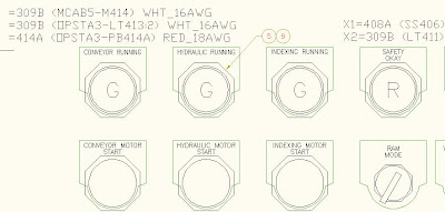
After you add wire numbers to your schematics, annotate panel footprint symbols with this information. You can build panel footprint symbols with target attributes used for the wire connection information.
Let's Take a Look!!!
http://www.screencast.com/t/J4Zu2RFvf
Created by Dave one of the Cad Geeks
Well, I just got done downloading and installing all of the new Autodesk Manufacturing products. It was quite time consuming and a lot of data moving, but I am excited as always to explore all of the new products as well the enhanced new ones. I usually cover all of the Inventor enhancements, but I may slip a few other products here and there. The biggest reason for that, is the total Digital Prototyping Solution and the tight integration and interoperability of all of the manufacturing products. Here is a highlight of some of the full circle products:
ALIAS - For conceptual design
AutoCAD Inventor - Mechanical Design (Simulate, analyze, optimize)
AutoCAD Electrical - Schematic design
Showcase - Real time rendering (Concept design review)
Navisworks - Factory simulation/automation
Vault - Data Collaboration
As you can see, Autodesk has a product from concept to the manufacturing floor....and the great thing is....you can share the data between all team members in your organization without the need for multiple platforms or vendors. The solution is attainable, scalable and cost effective. I have a lot of tools to choose from when I walk into a customer, and it's exciting that Autodesk has given us the right tools for the job at hand. I'd hate it if I just had a hammer.... and a nail..... and a board.....nevermind. In upcoming posts, I will show the seamless integration of the Autodesk 2010 Manufacturing solutions and how they can help your business be more successful.
Cheers,
CAD Geek John
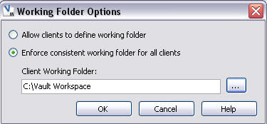
If you are anything like me, when trying to set up a bunch of workstations in identical configurations, you are bound to wind up with different settings on accident. This is commonly the case when setting up Vault as well. One of the settings that should be common between all the client workstations is the Working Folder or what we commonly call the "Workspace". By default, the working folder can be defined independently on each workstation, and each user could change their working folder location to be any location they desire. Obviously this can lead to problems when trying to manage an environment with more than a couple users. The solution is to define a rigid working folder location in the Administration settings.

By switching to the "Enforce consistent working folder for all clients" option and defining an explicit path for all clients to use, a lot of confusion can potentially be avoided in the future.

Contributed by Ben of the CAD Geeks

In this weeks video I will show you how to use the Check Model Tool to determine if you have any duplicate surfaces in your model. Then I will show you how to easily separate them from your model so you can delete them.
Click HERE to watch the video
Created by Aaron... Your Alias CAD Geek

